---
title: Read/write 25XX NOR flash via SPI protocol
x-toc-enable: true
...
**VOLTAGE WARNING**
------------------
**WARNING: Do NOT assume that the voltage is 3.3v on what you're flashing.
Lots of modern flash chips today are 1.8v on a lot of newer systems. Please
always check the letting on the chip and then look up a datasheet, to tell
exactly what voltage it's rated for; measuring with a volt meter would also
be prudent.**
**CAN'T GET A VALID READ??**
---------------------------
On systems that have two flash chips, MISO/MOSI are shared on a common line
hooked up to the PCH, but each flash has its own chip select. The PCH will
turn each chip on and off as required, when reading to or writing to a certain
chip. When externally flashing, both chip selects may be floating, so both
chips may be active.
In practice, many boards may place a small amount of resistance between
MISO/MOSI between the two flashes, such that the floating clip select isn't
really all that bad. When you hook up your flasher, you will typically control
the chipselect on the one you're flashing, but again the chip select on the
other flash may be floating.
Chip select is active low, so pulling it high turns off the chip. Assuming you
don't have other issues, e.g. bad wires, or wires too long, or unreliable
flasher, you should rule that out and pull the other chipselect high. E.g.
if you're flashing SPI1, make sure SPI2's chipselect is held high (shorted
to 3.3v).
Other than that, you should also check that your flasher has good drive level,
e.g. CH341a is pretty weak for in-system programming and should not be used
in most cases.
It they both fit, you could just use a 2nd clip on the other chip you want
to turn off, and control the chip select using that.
Trouble?
----------
Inquiries can be made via [RBoot IRC](../../contact.md) and other channels.
Install libre BIOS/UEFI firmware
--------------------------------------
This guide is predominantly about *installing RBoot* (flashing it) onto
your motherboard's main system flash. You can also adapt this guide for dumping,
erasing and verifying firmware images; this guide shows you how to use
the [flashprog](https://flashprog.org/) software with various external
25XX NOR flash programmers. This guide applies mostly to users of the
[GNU/Linux-libre operating system](https://www.gnu.org/distros/).
**Please ensure that your programmer's voltage matches that of the flash IC,
and read this guide carefully to account for proper electrical safety. In
general, these programmers operate at 3.3v, so you'll need a logic level
adapter and e.g. buck converter, if you're dealing with a 1.8V flash IC.**
This guide will teach you how to use various tools for externally reprogramming
a 25xx NOR flash via SPI protocol. This is the most common type of flash IC for
computers that coreboot runs on. Almost every system currently supported by
RBoot uses this type of boot flash.
We will be using
the [flashprog](https://flashprog.org/) software which is written to
dump, erase and rewrite these flash chips.
RBoot currently documents how to use these SPI programmers:
* Raspberry Pi Pico (RP2040)
Many other SPI programmers exist. More of them will be documented on this page,
at a date in the future. You can otherwise figure it out on your own; certain
parts of this page are still useful, even if you're using a programmer that
RBoot does not yet document.
Most systems in RBoot have to be re-flashed externally, using instructions
on this and similar guides, the first time you flash. However, on all currently
supported systems, it's possible that you can re-flash *internally* when
RBoot is running.
*Internal* flashing means that the host CPU on your system can re-program the
SPI flash, using an on-board SPI programmer (which all boards have). You do this
from a GNU/Linux-libre operating system, with flashprog.
*This* guide that you're reading now is for using an *external* programmer. It
is called *external* because it's not the *internal* one on your motherboard.
Raspberry Pi Pico
-----------------
### Pico 1 (RP2040) supported
Pico 2 (RP2530) support was removed, due to stability issues.
Pico 1 dongles work just fine (RP2040). Pinout:
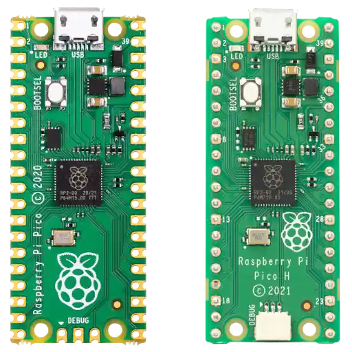
If you don't already have a programmer, get this one! It's well engineered,
safe, and costs just $5 with headers pre-soldered (Raspberry Pi Pico H).
Additionally, all the software running on it is free, down to the full
[Boot ROM](https://github.com/raspberrypi/pico-bootrom). The wireless
versions (Pico W & Pico WH) need vendor firmware to use the Wi-Fi chip,
but that is not needed for following this guide.
### Download serprog firmware pre-compiled
Find tarballs of serprog images in RBoot release archives.
### Build serprog firmware from source (OPTIONAL)
**Pre-compiled binaries are also available, in RBoot releases.**
You can also find the source code for these, under `src/` in RBoot release
archives (source code tarball), and/or under `src/` in `rbmk.git` if downloading
using the build instructions below.
Alternatively to the binaries, you
could build it yourself or you could also clone `rbmk.git` and [install build
dependencies](../build/#first-install-build-dependencies), then inside rbmk,
do:
./mk -b pico-serprog
This will automatically build the rpi-pico firmware, and the file will be
at `bin/serprog_pico/serprog_pico.uf2`
and `bin/serprog_pico/serprog_pico_w.uf2`.
### Install the serprog firmware
First, connect just the Pico to your computer with a micro-USB cable.
Mount it like any other USB flash drive. If it isn't detected, you might need
to press the BOOTSEL button while you plug it in (this forces it into the
bootloader mode).
When you have the build, or if you're using a release build, copy the
file `.uf2` file into your Pico. You must make sure to build the correct
target, or otherwise copy the correct file for your device.
### Logic levels
A Pico has proper 3.3V logic levels, unlike a ch341a. Which means it won't
destroy your board by sending 5V to it. If you have a 1.8V flash chip,
you need to add a logic level converter. **Please ensure that you have matched
the voltage of your programmer to the voltage of your chip; both the data lines
and power lines to the chip must match.**
### Wiring
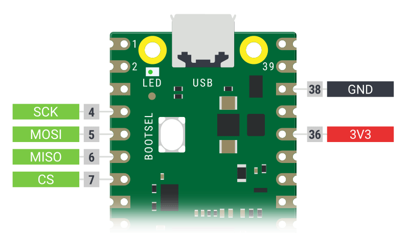
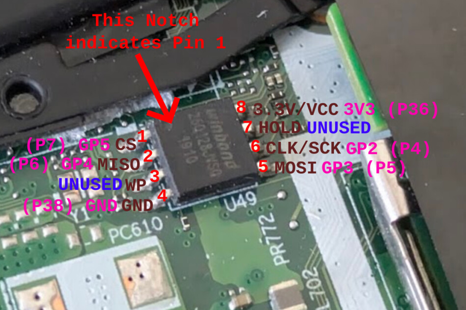
Disconnect the Pico and proceed to wire it to your
[flash chip](/docs/install/spi.html#identify-which-flash-type-you-have).
**NOTE: SCK and CLK mean the same thing. The diagram below says SCK, and other
parts of this guide say CLK. It's the same thing!**
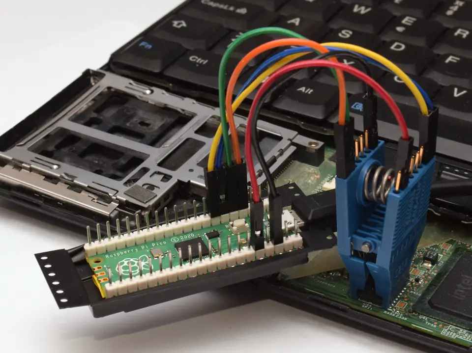
Headers were manually soldered on the top side, and the plastic packaging
was repurposed as an insulating base. These might be nice to have, but by no
means necessary. If your headers are on the other side, just keep in mind
that the pinouts are as seen from above.
Now run (as root) `dmesg -wH`. When you plug in the Pico, a line like this
will appear:
[453876.669019] cdc_acm 2-1.2:1.0: ttyACMx: USB ACM device
Take note of the ttyACMx. Flashprog is now usable
(substitute ttyACMx with what you observed earlier).
flashprog -p serprog:dev=/dev/ttyACMx,spispeed=16M
spispeed=32M usually works, but since it's not much faster it's probably
not worth it. The 12Mbps USB port is limiting the actual speed here.
Higher speeds might work nicely, on Pico 2.
Do not buy CH341A!
------------------
NOR flashes on RBoot systems run on 3.3V DC or 1.8V DC, and this includes
data lines. CH341A can have 5V logic levels on data lines, which can damage your
SPI flash and also the southbridge that it's connected to, plus anything else
that it's connected to.
These ch341a programmers are unfortunately very popular. DO NOT use it unless
you have fixed the issue. You CAN fix it so that the data lines are 3.3v, if
you follow the notes here:
In practice, most people will not fix their ch341a and instead just risk it,
so no documentation will be provided for ch341a on this website. It is best
to discourage use of that device.
**Not covered on that eevblog page: the WP/HOLD pins (pins 3 and 7) must be
held high via pull-up resistors, but on CH341A dongles, they are directly
connected to 3.3V DC (continuity with pin 8). It is advisable to cut these
two connections, to the WP and HOLD pins, and jump the cuts using pull-up
resistors instead. A value between 1k to 10k (ohms) should be fine.**
**In the event of a surge, like for example you connect the clip wrongly and
cause a short circuit between two pins, lack of pull-up resistors on WP/HOLD
could cause a direct short between VCC/ground, which would cause a lot of heat
build up and possibly fire (and definitely damaged circuitry). On SOIC8, pin 3
is WP and 4 is GND, so a direct 3.3v connection there is quite hazardous for
that reason; all the more reason to use a pull-up resistor.**
The motherboard that you want to flash (if using e.g. pomona clip) will probably
have pull-up resistors on it already for WP/HOLD, so simply cutting WP/HOLD
on the CH341A would also be acceptable. The pull-up resistors that you
place (in such a mod) on the CH341A are only useful if you also want to flash
chips in the ZIF socket. If pull-up resistors exist both on e.g. the laptop
motherboard and on the CH341A, it just means the equivalent series resistance
will be of the two resistors (on each line) in parallel. If we assume that
a laptop is likely to have a resistor size of ~3.3k for pull-ups, then a value
of ~5.6k ohms on the CH341A side seems reasonable.
Alternatively, you might work around the voltage issue by using an adapter with
logic-level converter, making sure to have matching vcc going into the flash.
Use of a logic level converter would be quite flexible, in this scenario, and
you could use it to set many voltages such as 1.8v or 3.3v.
In case it's not clear:
**Please do not buy the ch341a!** It is incorrectly engineered for the purpose
of ROM flashing on systems with 3.3v SPI (which is most coreboot systems). DO
NOT USE IT! This issue still isn't fixed by the manufacturer, and it doesn't
look like they will ever fix it.
If you see someone talking about CH341A, please direct them to this page and
tell them why the CH341A is bad.
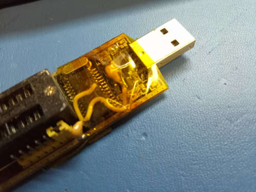
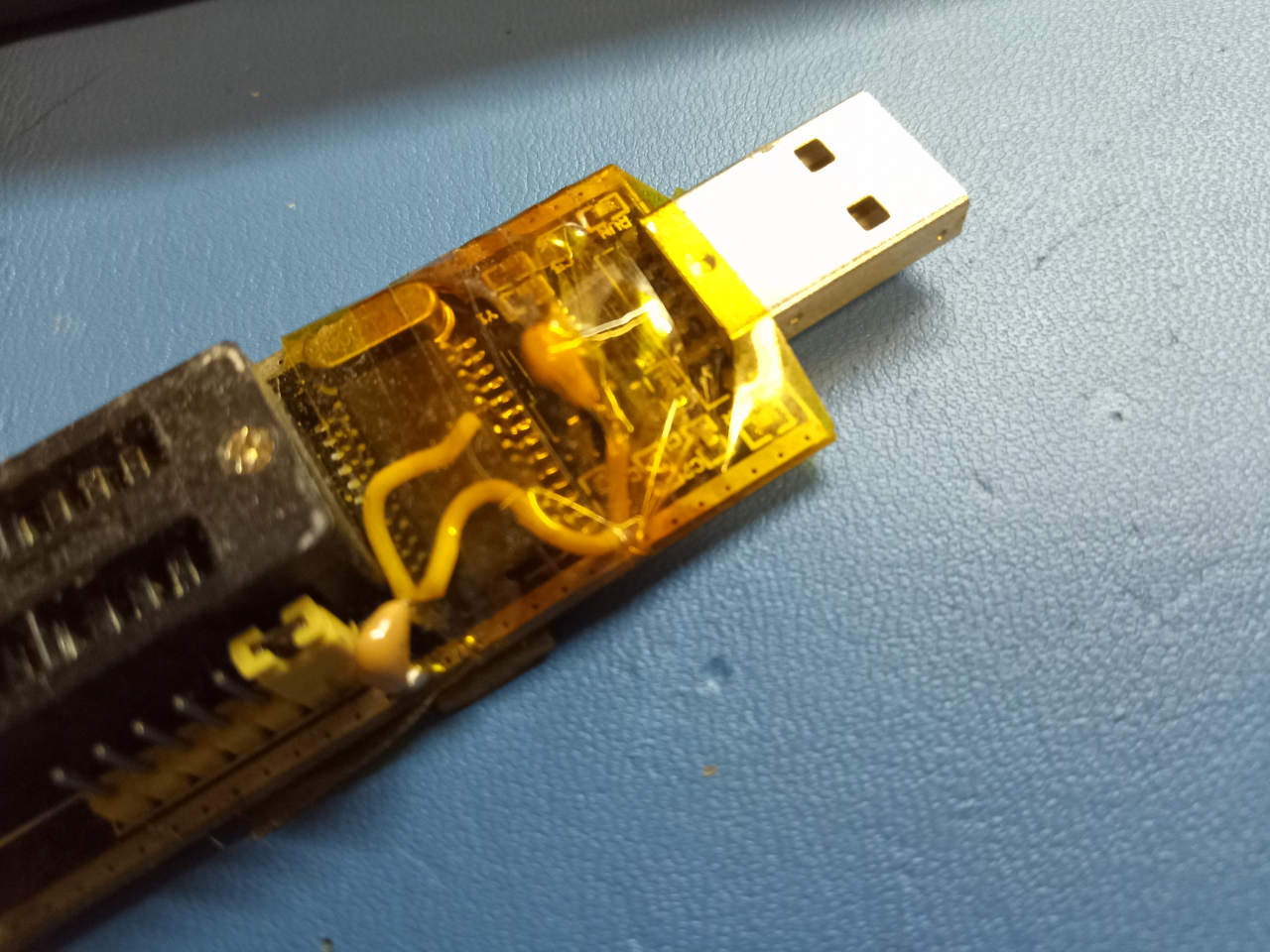
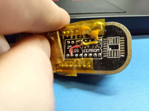
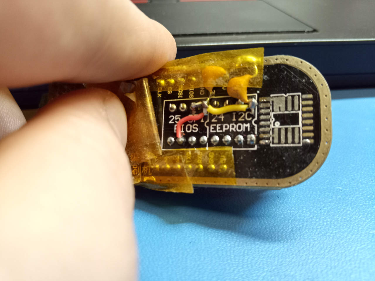
These photos show both modifications (3.3v logic and WP/HOLD pull-up
resistors) performed, on the black CH341A:\
 The green version (not shown above) may come with 3.3v logic already wired, but
still needs to have pull-up resistors placed for WP/HOLD. Some of them may have
switchable voltage instead, via a physical toggle on the board.
Disclaimer: A few (not many, but wily) people have criticised this section of the
documentation, due to a misconception about what it really means and also because
this section was previously very poorly written. So to be clear:
Yes, we are quite well aware that the CH341A can in fact operate at 3.3v,
even unmodified black models; the VCC line is 3.3v, and if when you either
directly wire VCC to WP/HOLD pins yourself, or a pull-up resistor on the
motherboard you're flashing pulls these high at 3.3v, then the logic levels
on the data lines do in fact switch to 3V *during an erase, read or write cycle*.
When no flashing operation is underway, the data lines are outputting at almost
negligable current, so the actual amount of heat generated will be negligable,
and therefore damage is unlikely. However, as stated above and as we will state
again:
* This is bad electrical design. The CH341A can switch flexibly between 3V
and 5V operation, but most flashes today are 1.8V or 3V anyway, and there are
all kinds of scenarios (such as over-current or surge event) where this 5V
idle logic level could still be applied. Modifying your CH341a to 3.3v
only, as defined in the datasheet (and by this page) is highly recommended.
* The drive level is extremely poor anyway, on CH341a, making ISP-based
flashing ill advisable in many cases, such as where the PCH (Intel platforms)
is partly active and the data lines have lower resistance, because some
boards have 0ohms or very low resistance on these lines.
* No pull-ups on the WP/hold lines, when flashing in the socket; they are high
via 0ohm trace to VCC, whereas you are advised to use a pull-up resistor to
mitigate over-current events.
* Crap LDO on the board, and no ESD/overcurrent protection; the CH341a probably
can't provide much current on the VCC line, especially for ISP-based flashing
where the flash shares a common power rail with many other components.
CH341a is cheap junk. Get yourself a Raspberry Pi Pico instead; it's about the
same price, but of much higher quality from an electrical design perspective,
supports much higher (12mA!) drive levels on data lines, can control multiple
chip selects at once; it's just better, in every way. And the Raspberry Pi is
completely reprogrammable, so you can use it for something else when you're
done, e.g. UART dongle, or if you're wily enough, [PlayStation 1 Optical Disc
Emulator](https://github.com/paulocode/picostation) - the Pico is simply a
highly versatile tool, much better value for money.
There is only one instance where the CH341a is *good*, and that is when you're
actually flashing a loose (not soldered) chip, in the ZIF socket on the CH341a
board. It's a DIP-8 socket, and you can also buy WSON-8 and SOIC-8 or SOIC-16
adapters for it; you can also plug a special adapter board into it that converts
the voltages (VCC and data lines) to 1.8V, for 1.8V flashes (you could also
use that same 1.8V adapter circuit in a breadboard wired to your Pico). On
socket-based flashing, *which is specifically what the CH341a was designed
for*, you don't have to worry about weak drive level because there is nothing
contending with it on the flash IC's data pins.
The *socket-based* flashing operation is what we recommend this programmer
for, *only if you already have one*. We still recommend fixing the issue with
the WP/HOLD pins as described above; if you're doing this, note that there are
also newer models that have a voltage switch and logic level shifter already
on the board, which can be very useful. *Clip-based* flashing (ISP / in-system
programming) is, specifically, what we advise against using the CH341a for.
Why pay $10 for a CH341a when you can pay $10 for a Raspberry Pi Pico which is
electrically and functionally superior in every way? And the Pico is completely
libre, right down to the boot rom.
Identify which flash type you have
----------------------------------
In all of them, a dot or marking shows pin 1 (in the case of WSON8, pad 1).
Use the following photos and then look at your board. When you've figured out
what type of chip you have, use that knowledge and the rest of this guide, to
accomplish your goal, which is to read from and/or write to the boot flash.
### SOIC8
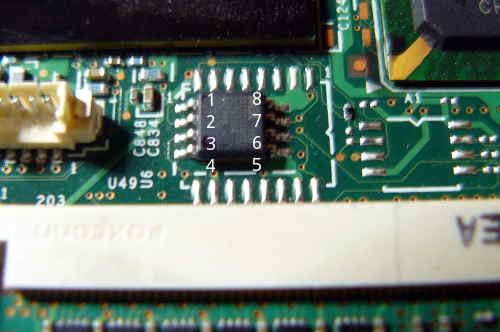
| Pin | Function |
|-----|----------|
| 1 | CS |
| 2 | MISO |
| 3 | WP |
| 4 | GND |
| 5 | MOSI |
| 6 | CLK |
| 7 | HOLD |
| 8 | VCC |
### SOIC16
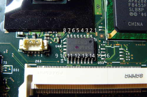
| Pin | Function |
|-----|----------|
| 1 | HOLD |
| 2 | VCC |
| 7 | CS |
| 8 | MISO |
| 9 | WP |
| 10 | GND |
| 15 | MOSI |
| 16 | CLK |
SOIC8 and SOIC16 are the most common types, but there are others:
### WSON8
It will be like this on an X200S or X200 Tablet:\
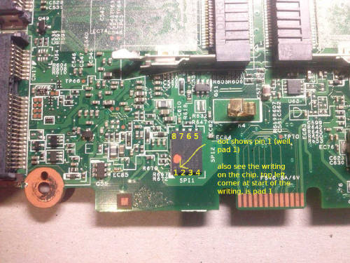
Pinout is the same as SOIC8 above.
On T400S, it is in this location near the RAM:\
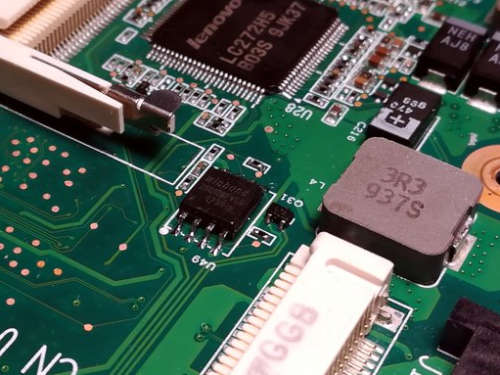\
NOTE: in this photo, the chip has been replaced with SOIC8
### DIP8
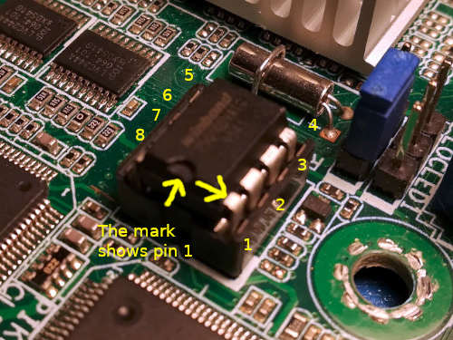
Pinout is the same as SOIC8 above.
### Supply Voltage
Historically, all boards that RBoot supports happened to have SPI NOR chips
which work at 3.3V DC. With the recent addition of Chromebooks whose chips are
rated for 1.8V DC, this can no longer be assumed.
Inspect the chip on your board for a part number, look up the datasheet for it.
Find out and make note of the power supply voltage it needs. If it doesn't
match the voltage output by your external flashing hardware, you should only
connect it to the chip through an adapter or logic level converter, never
directly.
Software configuration
----------------------
### Install flashprog
Flashprog is the software that you will use, for dumping, erasing and rewriting
the contents of your NOR flash.
In the RBoot build system, from the Git repository, you can download and
install flashprog. Do this after downloading the
[rbmk Git repository](../../git.md):
cd rbmk
sudo ./mk dependencies parabola
NOTE: other distros are in `config/dependencies/` - check there and replace
parabola with whatever you want, based on the list of files in there.
You need flashprog:
./mk -b flashprog
Find it then under `elf/flashprog/`
If you're flashing a Macronix flashchip on a ThinkPad X200, you will want to
use a special patched version of flashprog, which you can download like so
in rbmk:
./mk -b flashprog
Patched source code is compiled, and a
binary is also available that you can simply run. Pass the `--workaround-mx`
argument in flashprog. This mitigates stability issues.
Example usage:
./elf/flashprog/flashprog -p PROGRAMMER --workaround-mx
How to use flashprog
--------------------
Read past these sections, further down this page, to learn about specific chip
types and how to wire them.
### Reading
Before flashing a new ROM image, it is highly advisable that you dump the
current chip contents to a file.
Run this command to see if 25xx flash is detected, with your RPi properly
wired.
sudo ./flashprog -p serprog:dev=/dev/ttyACMx,spispeed=16M
NOTE: On some systems, higher speeds will be unstable. On those systems, try
lower speed like `spispeed=4096` or even `spispeed=2048` which should, in most
cases, work just fine but it will obviously be slower. The `spispeed=32768`
setting works just fine on most setups if you use short wires, within 10cm.
If flash chip is detected you may try reading (dumping) the flash contents now,
or you can try flashing it with a new ROM.
Dump it like so (pico):
sudo ./flashprog -p serprog:dev=/dev/ttyACMx,spispeed=16M -r dump.bin
It is advisable to take a *2nd* dump, e.g. `dump2.bin`, and then check sha1sum:
sha1sum dump*.bin
If the checksums match, it indicates that you have a good dump. If they do not,
check your wiring. Wires should be within 10cm length for best stability, and
they should all be the same length (VCC and GND wires can be longer).
This advice is *especially* applicable to the BBB, which is highly unreliable.
For boards with more than one flash chip you will need to read from both chips
and combine them into a single file.
Most of the time, a two chip setup includes one 8mb chip (SPI1) and one 4mb (SPI2)
chip. SPI1 is the first 8MB of the ROM image in this example.
The setup just described applies to the x230, t430, t530, and t440p.
For other boards, make sure you know which chip contains the lower and upper
portions of the rom.
You can combine both flashes together with `cat` for example:
cat spi1_8mb.rom spi2_4mb.rom > full_12mb.rom
Note that you will need this combined rom if you intend to manually extract vendor
files, which is a method not officially supported by RBoot's build system.
### Writing
Next, run this command (pico):
sudo ./flashprog -p serprog:dev=/dev/ttyACMx,spispeed=16M -w /path/to/rboot.rom
Again, use a lower `spispeed` value if you need to, for stability.
Once that command outputs the following, the flash has completed
successfully. If not, just flash again.
```
Reading old flash chip contents... done.
Erasing and writing flash chip... Erase/write done.
Verifying flash... VERIFIED.
```
If it says "VERIFIED" or says that the chip contents are identical to the
requested image, then the chip is properly flashed.
If the board you are writing to has two chips you'll need to split the rom into
two sections.
For example, to split a rom for the 12MB flash setups:
dd if=rboot_12mb.rom bs=1M of=spi1_8mb.rom count=8
dd if=rboot_12mb.rom bs=1M of=spi2_4mb.rom skip=8
Flash the resulting roms to each of their respective chips according to the above instructions.
Hardware configuration
----------------------
Refer to the above guidance about software configuration. The following advice
will teach you how to wire each type of flash chip.
### WARNINGS
Do not connect the power source until your chip is otherwise properly
wired. For instance, do not connect a test clip that has power attached.
Do not *disconnect* your chip from the flasher until you've disconnected or
turned off the power source.
BE CAREFUL that you are indeed supplying the appropriate supply voltage to the
chip. SPI flashes on most of the currently supported RBoot hardware run on
3.3V DC and logic at that level too. Some of them (at least Chromebooks) can
have chips that run on 1.8V DC. You should make sure to check the part number
and datasheet of the SPI flash chip for the supply voltage it requires. If your
external flashing hardware doesn't match it, use an adapter or logic level
converter to flash.
It is important to CHECK that you are running on the correct voltage, when you
do anything with these chips. Lower than the rated supply voltage won't damage
anything, but higher will fry your chip (on most 3.3V chips, the tolerated
voltage range is between 2.7V and 3.6V, but 3.3V is the most ideal level).
DO NOT connect more than 1 DC power source to your flash chip either!
Mixing voltages like that can easily cause damage to your equipment, and to
your chip/motherboard.
### MISO/MOSI/CS/CLK lines
You may want to add 47ohm series resistors on these lines, when flashing the
chips. Only do it on those lines (NOT the VCC or GND lines). This provides
some protection from over-current. On Intel platforms, the SPI flash is usually
connected via such resistors, directly to the Southbridge chipset.
### ISP programming and VCC diode
ISP means in-system programming. It's when you flash a chip that is already
mounted to the motherboard of your computer that you wish to install RBoot
on.
It may be beneficial to modify the motherboard so that the SPI flash is powered
(on the VCC pin) through a diode, but please note: a diode will cause a voltage
drop. The tolerated range for a chip expecting 3.3V VCC is usually around 2.7V
to 3.6V DC, and the drop may cause the voltage to fall outside that. If you do
this, please also ensure that the WP and HOLD pins are still held to a high
logic state; each via their own resistor (1K to 10K ohms) connected to the
*same* power source going through the diode.
The reason is simple: on most systems, the flash shares a common power rail
with many other components on the board, which draw a lot of current. Further,
if you accidentally provide too much voltage or cause an overcurrent, you could
fry those other components but if there is diode protection, you'll only fry
the boot flash (and it is very easy to replace, if you have good soldering
skills).
When you've placed the diode, ensure that VCC on the chip is isolated from all
other components on that board, which share the same power rail. Further,
ensure that the pull-up resistors for WP/HOLD are *only* connected to the side
of the diode that has continuity with the VCC pin (this is important because if
they're not, they won't be held high while doing ISP flashing, even if they're
still held high when the motherboard is fully powered on).
Furthermore: ensure that the SPI flash is operating at the appropriate supply
voltage (2.7V to 3.6V for a 3.3V chip) when fully powered on, after installing
the diode.
If it's a desktop/workstation/server board (not a laptop), you could de-solder
the SOIC8/WSON8 if it uses that, and replace with an IC socket (for SOIC8,
WSON8 or DIP8, whatever you want), because then you could easily just insert
the flash into a breadboard when flashing.
TODO: Make a page on rboot.org, showing how to do this on all motherboards
supported by rboot.
### Pull-up resistors and decoupling capacitors
**Do this for chips mounted to a breadboard. Ignore this section if you're
flashing a chip that is already soldered to a motherboard.**
This section is only relevant if you're flashing a new chip that is not yet
mounted to a motherboard. You need pull-up resistors on the WP and HOLD pins,
and decoupling capacitors on the VCC pin. If the chip is already mounted to a
board, whether soldered or in a socket, these capacitors and resistors will
probably already exist on the board and you can just flash it without pulling
WP/HOLD high, and without capacitors(just connect your external power source).
The best way is as follows:
* Insert the DIP8 IC into a breadboard (2.54mm holes), if it's DIP8
* Insert WSON8 into a WSON8 socket and put on a breadboard, if WSON8
* Insert SOIC8 into a SOIC8 socket and put on a broadboard, if SOIN8
* Wire an SPI flasher, using 2.54mm dupont leads, to the breadboard, using
the correct wiring (see link to SPI flashing guides below)
SOIC8/WSON8/DIP8: pin 3 and 7 must be held to a high logic state, which means
that each pin has its own pull-up resistor to VCC (from the voltage plane that
pin 8 connects to); anything from 1Kohm to 10Kohm will do. When you're flashing
a chip that's already on a laptop/desktop/server motherboard, pin 3 and 7 are
likely already held high, so you don't need to bother.
SOIC8/WSON8/DIP8: pin 8, which is VCC, will already have decoupling capacitors on it
if the chip is on a motherboard, but lone chip flashing means that these capacitors
do not exist. A capacitor passes AC but blocks DC. Due to electromagnetic
indunctance, and RF noise from high-speed switching ICs, a DC voltage line isn't
actually straight (when viewed on an oscilloscope), but actually has low voltage
AC mixed in; on a particularly noisy line under high load, noise of around 300mV
or more is common. To smooth out that noise, you wire capacitors from the DC
line to ground, with the side of the capacitor on VCC as close to the IC's VCC
pin as possible. We recommend that you use ceramic capacitors for this purpose.
The recommended capacitors for this are: 100nF and 4.7uF ceramic capacitors.
Electrolytic capacitors are inferior for this, because they have higher ESR
(ceramic capacitors have super low ESR, which is very good for decoupling).
The result of using a decoupling capacitor is that some of the noise on the DC
line is filtered to ground, making the DC signal much cleaner/straighter (when
seen on an oscilloscope).
SOIC16: same as above, but use a SOIC16 socked on a breadboard. On SOIC16,
WP/HOLD are not pin 3/7 like above, but instead pins 1 and 9, so wire your
pull-up resistors on those. VCC on SOIC16 is pin 2, so wire your decoupling
capacitors up on that.
### SOIC8/WSON8/DIP8/SOIC16 not mounted to a motherboard
If your system has lower capacity SPI flash, you can upgrade. On *most* systems,
SPI flash is memory mapped and the maximum (in practice) that you can use is a
16MiB chip. For example, KGPE-D16 and KCMA-D8 motherboards in rboot have
2MiB flash by default, but you can easily upgrade these. Another example is the
ThinkPad X200S, X200 Tablet and T400S, all of which have WSON8 where the best
course of action is to replace it with a SOIC8 flash chip.
In all such cases, flashing a new chip should be done using a breadboard, not
a test clip. You will use 2.54mm dupont leads to connect your Raspberry Pi.
For data lines, make sure that all wires are the same length, and about 10cm
in length (don't use longer lengths than this).
Some advice:
* DIP8: Strong choice is Winbond W25Q128FVIQ. It is a direct drop-in replacement
* SOIC8 is possible: Winbond W25Q128FVSIG is a strong choice.
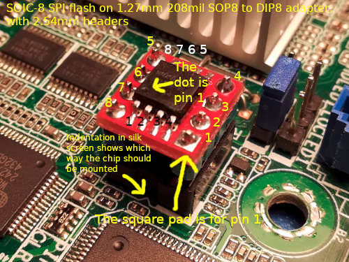
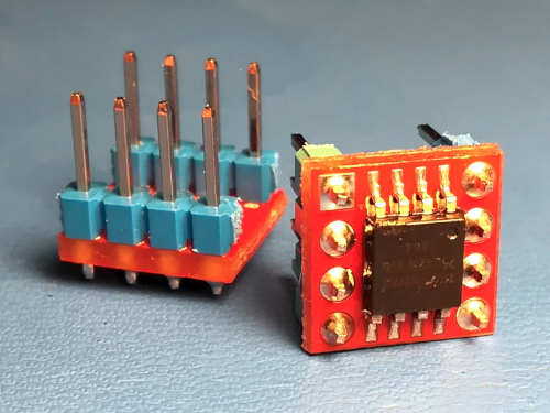
* DIP8 using adapter and SOIC8 is also possible. Use a 208-mil 1.27mm SOP8/SOIC8
to DIP8 adapter PCB with a
2.54mm 4-pin header on each side (square pins), then you can slot that in as
though it were a normal P-DIP 8 IC. This page shows a perfect example:
* The above SOP8/DIP8 adapter is actually what we recommend, if you're going
that route. It's made by Sparkfun and widely available; you don't have to buy
from that particular website. The part number is: BOB-13655
* If you use a SOP/DIP adapter with a SOIC8 IC, you'll have to solder it
obviously. K tip is a nice choice for soldering ICs like these. Use good
flux and 60/40 leaded solder (or 63/37), none of that Rohs lead-free crap.
If you go for a SOIC8, mounted it to the SOP to DIP adapter (208mil 1.27mm one)
and solder 2.54mm headers to it. You could put the 2.54mm pins in a breadboard,
then solder the chip to the adapter PCB and mount that to the pins on the
breadboard, to keep it aligned, and solder that. Whith the PCB on the pins, and
the pins in the breadboard, push the pins inwards a little bit.
This is for a new SOIC8 chip, but you can get sockets similar to the one in the
video, but for WSON8. Sometimes they are called DFN8 or QFN8 sockets. Get one
that is 1.27mm pitch.
If you're flashing/dumping a lone WSON8, get a WSON8/QFN8/DFN8 socket (1.27mm
pitch) and mount it to a breadboard for flashing. If your motherboard's landing
pads for the flash IC can take a SOIC8, we recommend that you use a SOIC8
instead because a test clip is possible later on when you wish to re-flash it,
however you may be dealing with a board where replacing existing WSON8 with
SOIC8 is desirable; in that case, you might still want to dump the contents of
the original WSON8.
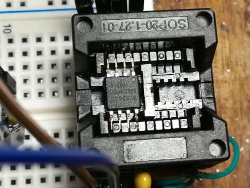
Here is a SOIC8 in a socket, mounted to a breadboard, for flashing:\
Here is a photo of a DIP8 IC:\

Here is a photo of a SOIC8 in 1.27mm 208mil SOP to DIP adapter:\
NOTE: DIP8 and WSON8-in-socket, and SOIC16-in-socket, are basically the same,
just adapt accordingly.
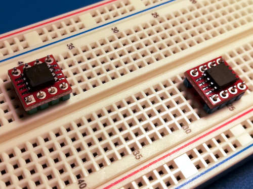
If you're replacing a DIP8 but using SOIC8 on an adapter, solder it to the
adapter first, then insert 2.54mm headers (square pins) into a breadboard to
keep them aligned. Put the SOIC8 on the PCB, onto the pins, and push the pins
inwards a little bit, and solder that. Alternatively to the breadboard, you
can just put the 2.54mm pins directly in the DIP8 socket and mount the SOIC8 +
adapter onto that, and solder that. Use quality rosin flux (not acid based)
and good 60/40 or 63/37 leaded solder (don't use lead-free):

### SOIC8/SOIC16 soldered to a motherboard
This is an example of *in-system programming* or *ISP* for short.
SOIC8:\
Pomona 5250 is a SOIC8 test clip. There are others available, but this is the
best one. Use that. Use the SOIC8 diagram (see above) to wire up your Raspberry
Pi.
Your motherboard likely already pulls WP/HOLD (pins 3 and 7) high, so don't
connect these. VCC on SOIC8's pin 8 probably already has decoupling
capacitors on the motherboard, so just hook that up without using a capacitor.
SOIC16:\
Pomona 5252 is a SOIC16 test clip. There are others available, but this is the
best one. Use that. Use the SOIC16 diagram (see above) to wire up your Raspberry
Pi. WP/HOLD pins are pins 1 and 9, and likely already held high, so no pull-up
resistors needed. You do not need a decoupling capacitor for pin 2 (VCC) either
because the motherboard will already have one.
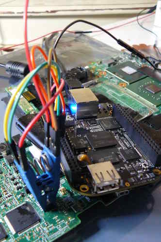
Here is an example of a test clip connected for SOIC16:\

And here is an example photo for SOIC8:\
### DIP8 soldered to the motherboard
It is extremely cursed for DIP8 to be soldered directly to the motherboard. It is
usually mounted to a socket.
The pins are large enough that you can just use test hooks to wire up your chip
for flashing. You might want to de-solder the chip, using a solder vacuum
(extractor) tool, and then you can install a socket in its place. You can then
insert the DIP8 IC into the socket.
In the RBoot project, we have never heard of a board where the DIP8 is
directly soldered. It is almost always mounted in a socket.
Your DIP8 IC has the same pinout as a SOIC8 IC.
### Replace WSON8 IC with SOIC8
**NOTE: You can alternatively purchase WSON8 probes from a site like Aliexpress.
They look similar to SOIC8 clips, and they work similarly.**
You *can* connect a SOIC8 test clip, but you will struggle to get good
connections and it will be extremely unreliable. DO NOT solder to the pads of
the WSON8 directly; some people do this, but you shouldn't do it, because you
can easily damage the pads that way.
WSON8 has the same pinout as SOIC8, but it's a ball mounted QFN (quad flat
pack, no leads). There are no clips for it. Sometimes referred to as QFN8
On all currently supported RBoot hardware, boards that have WSON8 can also
have a SOIC8 because the pads are long enough to accomodate either type of
chip.
A good choice of soldering iron would be a T12-D08 or T12-K tip, on a T12
soldering station. KSGER makes nice soldering stations:\
The case on that KSGER station is not grounded by default, so you should
modify it to ground the case, in case of an electrical fault. This is for your
safety. This video shows how to do it:\
Use quality 60/40 or 63/37 lead+tin solder. Do not use lead-free! Lead-free is
not suitable for hobbyist use such as this. Use quality *rosin* flux. Fluxes
with an acid base should never be used. Amtech and MG Chemicals make good flux
pastes. Use it in a dispenser tube. Some of these fluxes will contain adapic
acid which has a low pH level, and it is simply used as a mild activator. So
long as you clean the flux afterwards, you should be fine.
Make sure to have a copper wire brush and a wet sponge handy. You wipe the iron
on the wire brush and tap it on the wet sponge(to remove oxides) to keep it
clean. Always clean your tip constantly. Also, after cleaning it, always re-tin
the tip with fresh solder, to prevent the tip from oxidizing!
Make sure to buy 99.9% isopropyl alcohol. Don't buy weaker solutions because
they contain water, and don't use other chemicals because most other chemicals
are corrosive. You use the isopropyl to clean the area you're soldering, before
soldering it, and then soak up the wet alcohol with a cloth. You will also use
it to clean off any flux that you used.
Use of flux is very important, to get a good solder joint, because it removes
oxides and prevents further oxidation during soldering, ensuring that the solder
flows properly, otherwise the solder will ball up and you won't get a good
joint.
In case you're not comfortable with soldering, we have some excellent videos
linked on the [FAQ page](../../faq.md) which you can watch.
WSON8 IC:\
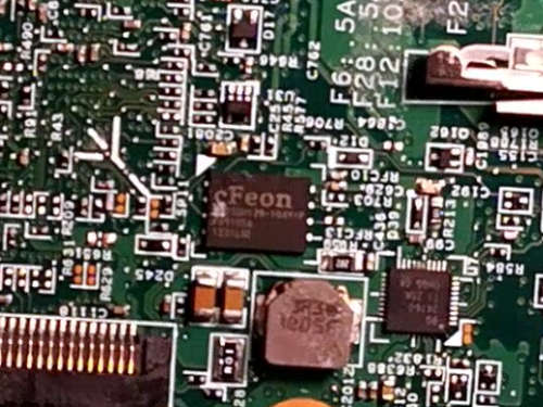
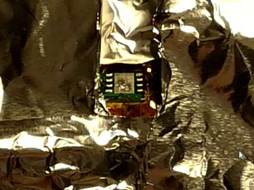
Surround a large area around the chip with layers of kapton tape, and then
aluminium foil. This will act as a heat shield, to reduce the risk of re-flowing
other solder joints (which can make them turn into cold joints, and you risk
knocking them off of the board):\
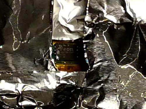\
Notice that the kapton+foil does not cover the chip itself, or the solder pads.
It's important that these are exposed to the heat.
Use a hot air rework station, set to about 330-340C. The reason for the higher
temperature is because air doesn't conduct heat as efficiently as an iron, so
you must use a higher temperature. You should put lots of rosin flux above the
IC. Do not hold the nozel too close to the board. The diameter of the nozel
should be slightly higher than the length of the chip. Apply even heat, at high
air flow.
While blasting the chip with hot air, hold the chip with tweezers but do not
use any real force. Do not try to forcefully pry off the chip. Simply hold the
chip with your tweezers, gently nudging it until it feels like the chip can
move freely. While in this state, the solder is fully melted and the chip can
be lifted off with ease.
If you're doing it correctly, the chip will come off within 1 minute, like so:\
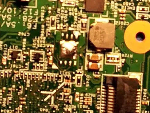
Add fresh solder to the pads, including the thermal pad:\
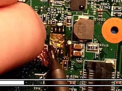
Now wick it out using a copper braid, dunked in rosin flux:\
Ensure that all of the solder is removed:\
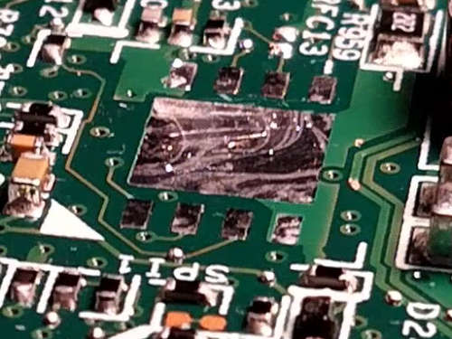\
You will notice that one of the pads doesn't have all of the solder removed.
The pad on the top-left in this photo. This is intentional, to show you a
comparison for reference. The other pads are free of solder.
You *can* simply solder the chip unflashed, and flash it using a test clip.
Alternatively, you can put the SOIC8 in a socket on a breadboard, and flash it
before soldering it. If you wish to dump the contents of the WSON8, you can
put the removed WSON8 in a socket on a breadboard and dump it using your
SPI flasher.
Align the new SOIC8, and tack it in the corner pins. Then solder it fully. Use
lots of flux!\
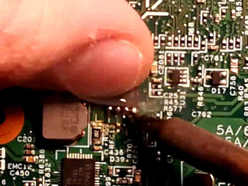\
A T12-D08 tip is being used in this photo, but a mini chisel, mini hoof or
knife (e.g. T12-K) tip would be ideal.
Ensure that all the joints are perfect. A good solder joint is shiny, and with
concave fillets where the solder has flowed. Observe:\
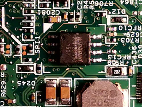
After you're done, use a soft bristle brush and 99.9% isopropyl alcohol to
break up the remaining flux, then soak up the flux using a cloth, while the
alcohol is still wet. 99.9% isopropyl is the best liquid to use, because it
evaporates quickly and it does not leave a corrosive residue.
-------------------------------------------------------------------------------
LICENSING
---------
This page is released under different copyright terms than most other pages
on this website.
This page and the photos on it are available under
[CC BY SA 4.0](https://creativecommons.org/licenses/by-sa/4.0/legalcode.txt)
Check the Git repository for history of who owns what part of the document.
Photos showing a BeagleBone Black are under the normal GFDL
license like other pages and images on this website, or you can use them under
the CC-BY-SA 4.0 license if you wish (I, *GNU Leah Rowe™*, own all BBB photos shown
on this page, except for the one on the beaglebone website, and that one is
merely linked here, instead of being hosted on the av.rboot.org server).
This version of the page is hosted in the `rbwww` git repository, with images
for it hosted in the `rbwww-img` repository (from RBoot).
[//]: # "SPDX-License-Identifier: GFDL-1.3-or-later"